
News

Forging Crankshafts: Process, Materials, Standards & Supplier Guide
 2026.04.23
 Industry news
Content
- 1 What Is Crankshaft Forging and Why It Matters
- 2 The Crankshaft Forging Process: Step by Step
- 3 Open-Die vs. Closed-Die Forging for Crankshafts
- 4 Material Selection: Which Steel Grade Is Right?
- 5 Forged vs. Cast Crankshafts: A Performance Comparison
- 6 Heat Treatment for Forged Crankshafts
- 7 Industry Standards and Quality Inspection
- 8 Industrial Applications of Forged Crankshafts
- 9 How to Choose a Forged Crankshaft Supplier
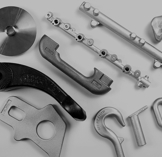
Every revolution of an engine crankshaft transmits enormous forces — gas pressure, inertia loads, and torsional stress — all at once. A crankshaft that cannot absorb these forces reliably will fail, and the consequences range from costly downtime to catastrophic equipment damage. That is precisely why forging, not casting, is the preferred manufacturing route for crankshafts used in demanding industrial and high-performance applications. The forging process aligns the internal grain structure of the steel to follow the shape of the part, producing a component that is fundamentally stronger than one poured into a mold.
This guide covers the complete picture of forged crankshafts: how they are made, which materials are used, how they compare to cast alternatives, what quality standards apply, and how to select the right supplier for your application.
What Is Crankshaft Forging and Why It Matters
A crankshaft converts the reciprocating motion of pistons into rotational power delivered to the drivetrain or driven equipment. To do this reliably across millions of cycles, the crankshaft must combine high tensile strength, excellent fatigue resistance, and surface wear resistance — all in a geometrically complex shape with throws, journals, and counterweights at precise angular positions.
Forging achieves these properties by shaping heated steel under controlled compressive force rather than pouring molten metal into a mold. The result is a continuous, unbroken grain flow that follows the contour of the part. Where a casting may contain porosity, shrinkage voids, or randomly oriented grain boundaries, a forging is dense and directionally strong. This difference is not merely theoretical — forged crankshafts typically exhibit elongation rates of 20–22% before failure, compared to 5% or less for nodular iron castings, making them far more resistant to sudden fracture under shock loading.
The Crankshaft Forging Process: Step by Step
Producing a forged crankshaft requires a carefully sequenced series of operations. Skipping or shortchanging any step affects the final mechanical properties. A typical closed-die production sequence runs as follows:
- Billet preparation and cutting — A bar of refined steel (commonly 45# carbon steel or alloy grades) is sawed to a precise weight that matches the forging's final mass plus trimming allowance.
- Heating — The billet is heated to approximately 1,150–1,250 °C (2,100–2,280 °F), at which point the steel becomes highly plastic without reaching a liquid state. Temperature uniformity across the billet is critical to prevent localized grain coarsening.
- Roll forging / preform blocking — The heated billet passes through roll-forging equipment to redistribute material and create a rough preform that approximates the crankshaft's zig-zag profile. This step reduces material waste in subsequent pressing operations.
- Pre-forging (blocker die) — The preform is placed into a blocker impression in the forging die. A first pressing gives the billet better definition, beginning to establish the throws and journals.
- Finish forging (finisher die) — The part is transferred to the finisher impression, where multi-ton press force squeezes it into the final near-net shape. The goal at this stage is to flow the metal — not simply compress it — so that grain lines follow the geometry of each crankpin and journal.
- Trimming — Flash (excess metal squeezed out along the die parting line) is removed in a trim press.
- Twisting or indexing — For multi-throw crankshafts, the throws must be set at specific angular positions (e.g., 90° for a four-cylinder engine). In twist-forging, a dedicated press rotates each throw to its required angle. Non-twist forgings use more complex die geometry to produce all throws in their final orientation in a single pressing — a method that better preserves grain continuity.
- Hot finishing and controlled cooling — The part is dimensionally corrected while still hot, then cooled under controlled conditions to prepare it for heat treatment.
- Heat treatment — Normalizing, tempering, quench-and-temper, or surface hardening processes are applied depending on the application requirements (see the heat treatment section below).
- Inspection and finishing — Shot peening, magnetic particle inspection, ultrasonic testing, and dimensional verification complete the process before the crankshaft moves to machining.
For a broader look at how process parameters affect forging outcomes, see our analysis of forging process characteristics in industrial manufacturing, and our comparison of hot forging versus cold forging across different industrial applications.
Open-Die vs. Closed-Die Forging for Crankshafts
Two fundamentally different die configurations are used to forge crankshafts, and the right choice depends on the size, complexity, and production volume of the part.
Closed-die (impression-die) forging uses matched dies that fully enclose the workpiece. Material is pressed into cavities machined into the die faces, producing parts with accurate dimensions, good surface finish, and minimal post-forge machining. It is the preferred method for high-volume automotive crankshafts and medium-sized industrial crankshafts where die investment costs are justified by production quantities. Material utilization is high, cycle times are short, and dimensional repeatability is excellent.
Open-die forging uses flat or simply shaped dies between which the operator manually repositions the workpiece at each hammer or press stroke. Because the dies never fully contain the part, open-die forging can produce very large crankshafts — some exceeding 3,000 lb (1,360 kg) in weight and 100 inches (2,540 mm) in length — that no closed-die press could accommodate. The trade-off is greater machining allowance and tighter operator skill requirements. Open-die forging is the standard approach for custom industrial crankshafts used in large compressors, heavy marine engines, and oil-field equipment.
In practice, many large crankshaft producers use a hybrid approach: open-die operations to rough-shape the part, followed by localized closed-die or ring-rolling steps to refine critical journal surfaces.
Material Selection: Which Steel Grade Is Right?
The steel grade chosen for a forged crankshaft determines its tensile strength ceiling, fatigue life, hardenability, and machinability. Selecting the correct grade from the outset avoids costly redesigns or premature field failures. The principal categories are:
| Grade | Type | Tensile Strength (psi) | Typical Application |
|---|---|---|---|
| 45# (C45) | Plain carbon steel | ~80,000–100,000 | Medium-load automotive and light industrial engines |
| 5140 | Chromium alloy steel | ~115,000 | Budget aftermarket; light-duty performance builds |
| 4130 / 4140 | Chromium-molybdenum steel | ~120,000–125,000 | Mid-range performance engines; moderate industrial loads |
| 4340 | Nickel-chromium-molybdenum steel | ~140,000–145,000 | High-performance engines, aerospace-adjacent applications, heavy industrial |
| Non-quenched & tempered (micro-alloy) | Micro-alloyed steel | Varies by grade | Green manufacturing; air-cooled after forging, no post-forge Q&T required |
4340 is the benchmark for demanding applications because its nickel content improves core toughness while chromium and molybdenum enhance hardenability and high-temperature strength. For applications where cost is a priority but strength requirements are moderate, 4140 offers a favorable balance. Non-quenched and tempered micro-alloy steels are gaining traction in Europe and Japan because they eliminate the energy-intensive quench-and-temper cycle, reducing both cost and environmental footprint — a meaningful advantage for high-volume crankshaft production.
For a comprehensive breakdown of forging steel grades across different industrial contexts, refer to our forging material guide covering types, properties, and selection criteria.
Forged vs. Cast Crankshafts: A Performance Comparison
The cast-versus-forged debate is frequently oversimplified. Both types can survive identical power levels under certain conditions. The real question is not "which survives a single run?" but "which delivers consistent reliability across millions of cycles under variable loading?"
| Parameter | Forged Steel | Cast Nodular Iron | Cast Steel |
|---|---|---|---|
| Tensile strength | 110,000–145,000+ psi | ~95,000 psi | ~105,000–110,000 psi |
| Elongation before failure | 20–22% | ~5% | ~6–8% |
| Grain structure | Continuous, directional flow | Random (isotropic) | Random (isotropic) |
| Internal porosity risk | Very low | Moderate | Low–moderate |
| Fatigue life | Excellent | Moderate | Good |
| Unit cost | Higher | Lower | Moderate |
For applications where the engine operates at sustained high loads — industrial compressors, marine propulsion systems, power generation sets — the superior ductility of a forged crankshaft is not a luxury. A cast crankshaft can survive indefinitely at moderate, consistent loads; push it into high-cycle fatigue territory with variable shock loading, and the lack of elongation becomes a fracture risk. For more detail on how these manufacturing methods differ in the context of heavy equipment components, see our article on casting vs. forging for engineering machinery parts.
Heat Treatment for Forged Crankshafts
Unlike cast iron cranks, whose journal surfaces work-harden naturally during machining, forged steel crankshafts require deliberate heat treatment to achieve the surface hardness and fatigue resistance needed for journal and pin surfaces. The three principal methods each address different application demands:
- Normalizing + tempering — The most common baseline treatment for medium-duty industrial crankshafts. Normalizing refines grain size after forging; subsequent tempering at a subcritical temperature relieves internal stresses and adjusts toughness. This sequence is specified under ASTM A983 for continuous grain flow crankshafts used in diesel and natural gas engines.
- Induction hardening — A high-frequency magnetic field rapidly heats the journal and crankpin surfaces to austenitizing temperature, after which they are quenched. The result is a hard, wear-resistant surface layer (typically 50–58 HRC) over a tough, ductile core. Induction hardening is fast, repeatable, and can be re-machined without full re-treatment — making it the preferred method for OEM automotive crankshafts and most industrial applications up to approximately 1,000 hp.
- Nitriding — A diffusion-based surface hardening process in which nitrogen is introduced into the steel surface at a relatively low temperature (around 500–560 °C). Nitriding produces an extremely hard surface layer without distorting the crankshaft's dimensions, making it ideal for precision crankshafts in high-boost, heavy-nitrous, or high-cycle-count applications where dimensional stability after heat treatment is critical. The process also improves corrosion resistance.
Shot peening is typically applied as a final step regardless of the heat treatment route. By inducing compressive residual stresses at the surface, shot peening significantly extends fatigue life at stress concentrations such as fillet radii — the most common crack initiation sites on crankshafts in service.
Industry Standards and Quality Inspection
Reputable forged crankshaft manufacturers work to internationally recognized specifications that define material chemistry, mechanical property requirements, and acceptable inspection methods. Understanding these standards helps buyers set clear acceptance criteria and avoid ambiguous purchase orders.
Two ASTM standards are particularly relevant:
- ASTM A983/A983M — Covers continuous grain flow forged carbon and alloy steel crankshafts for medium-speed diesel and natural gas engines. It specifies that the steel must be vacuum degassed, and mandates both normalizing-plus-tempering and quench-and-temper heat treatment options. Tensile, yield, elongation, reduction of area, Brinell hardness, and Charpy impact tests are all required at a frequency of one test per heat treatment load. Learn more at the official ASTM A983/A983M specification page.
- ASTM A456/A456M — Governs the magnetic particle examination of large crankshaft forgings with main bearing journals or crankpins 4 inches (200 mm) or larger in diameter. It defines three acceptance classes of increasing severity and categorizes inspection zones from major critical areas (journals and oil holes) through to less-stressed web surfaces. Full details are available at the ASTM A456/A456M standard specification.
Beyond magnetic particle inspection, ultrasonic testing (per ASTM A388) is used to detect internal volumetric discontinuities such as pipe, inclusions, or porosity that magnetic methods cannot find. For safety-critical applications — locomotive crankshafts, marine propulsion, gas compression — buyers should specify both surface and volumetric NDT as acceptance requirements.
Industrial Applications of Forged Crankshafts
While automotive crankshafts receive the most attention in popular technical literature, the majority of forged crankshaft value — in both unit cost and engineering complexity — lies in industrial machinery. Forged crankshafts serve critical functions across several sectors:
- Reciprocating compressors — Oil and gas transmission, refrigeration, and chemical process compressors depend on forged multi-throw crankshafts to convert motor rotation into piston-driven gas compression. These crankshafts operate continuously for years, often in corrosive or high-pressure-differential environments.
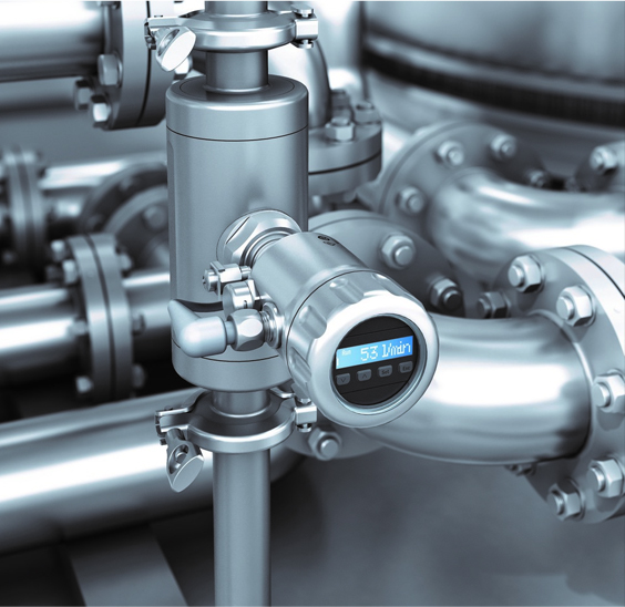
- Industrial pumps — High-pressure triplex and quintuplex pumps used in well stimulation, water injection, and fluid transfer rely on forged crankshafts to handle the intense radial and torsional loads generated at each piston stroke.
- Marine diesel engines — Large-bore, low-speed marine main engines use forged crankshafts that can weigh tens of thousands of pounds and span dozens of feet in length. Open-die forging is the only viable production method at these scales.
- Power generation — Diesel gensets and natural gas engines for off-grid and backup power generation require crankshafts that can sustain rated output for extended continuous runs — exactly the high-cycle-count regime where forged components outperform cast alternatives.
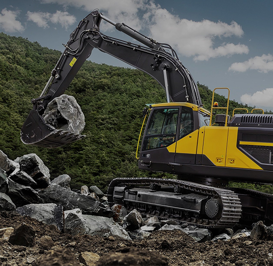
- Mining and construction equipment — Excavators, rock crushers, and drilling rigs subject crankshafts to severe shock and impact loading. The ductility advantage of forged steel directly translates into reduced catastrophic failure risk in these environments.
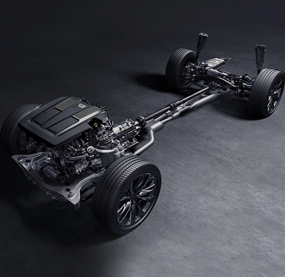
Our product range covers many of the adjacent forged components that work alongside crankshafts in these systems. Explore our engineering machinery forging solutions for construction and mining applications, our vehicle transmission system forgings for drivetrain-adjacent components, and our forged common rail components used in high-pressure fuel injection systems.
How to Choose a Forged Crankshaft Supplier
A forged crankshaft is not a commodity purchase. The supplier's process capability, materials knowledge, and quality infrastructure directly determine whether your crankshaft performs as engineered or fails prematurely. Evaluate potential suppliers against these criteria:
- Press capacity and die capability — Confirm that the supplier's press tonnage and die design capabilities match your crankshaft's size, throw count, and geometry. A supplier optimized for automotive cranks may lack the open-die capacity for large industrial shafts.
- Material traceability — Require full material certifications from the steel mill, including heat analysis, mechanical test results, and vacuum degassing confirmation for any crankshaft that must meet ASTM A983 or equivalent specifications.
- In-house heat treatment — Suppliers who perform heat treatment internally control more variables and can respond faster to process adjustments. Verify that their furnaces are qualified and temperature surveys current.
- NDT capabilities — Ask specifically which non-destructive testing methods the supplier performs in-house versus subcontracts, and which ASTM or equivalent standards they work to. Magnetic particle and ultrasonic testing should both be available.
- Lead time and inventory — For urgent replacements in critical production environments, a supplier with raw material inventory and forging press availability can mean the difference between days and months of downtime.
- Certifications — ISO 9001 is a baseline. For specific sectors (aerospace-adjacent, pressure equipment, rail), additional certifications such as AS9100, PED, or equivalent may be required.
- Custom engineering support — The best suppliers offer CAD/CAM-based forging die design services, allowing them to optimize grain flow and material utilization for your specific crankshaft geometry rather than adapting a standard die.
Getting these questions answered before placing an order — rather than after the first batch arrives — is the clearest differentiator between a reliable forging partnership and an expensive lesson in supply chain risk.

Our products primarily involve the production of forged components for the automotive industry, construction machinery industry, industrial instrumentation industry, and fluid equipment industry. Custom forging parts manufacturers and forged components solution providers in China.
Product links
Contact Us
-
Address:No. 5 Junrong Road, Daitou Town, Liyang City, Jiangsu Province, China
-
Tel:+86-18021979887
