
News

Forging Procedure: Step-by-Step Guide to the Metal Forging Process
 2026.05.09
 Industry news
Content
- 1 What Is the Forging Procedure?
- 2 Step 1: Die Design and Tooling
- 3 Step 2: Material Selection and Billet Preparation
- 4 Step 3: Heating the Workpiece
- 5 Step 4: Forging — Shaping Under Pressure
- 6 Step 5: Trimming and Flash Removal
- 7 Step 6: Heat Treatment
- 8 Step 7: Surface Finishing and Shot Blasting
- 9 Step 8: Inspection and Quality Control
- 10 Key Factors That Affect Forging Quality
What Is the Forging Procedure?
Forging is a metal shaping process in which compressive force — delivered by hammers, presses, or rolls — is applied to a heated or room-temperature workpiece to produce a component with a defined geometry. Unlike casting, which pours molten metal into a mold, forging works with solid metal and preserves and refines the material's internal grain flow, aligning it along the contours of the finished part. The result is superior tensile strength, fatigue resistance, and impact toughness compared to cast or machined equivalents.
The complete forging procedure moves through a sequence of well-defined stages: tooling design, material preparation, heating, pressure forming, trimming, heat treatment, surface finishing, and inspection. Each stage has specific process windows and control points that directly determine the dimensional accuracy and mechanical properties of the final component. Skipping or poorly executing any step introduces defects that are difficult — and costly — to correct downstream.
Step 1: Die Design and Tooling
The forging procedure begins long before any metal is touched. Die design sets the geometry of the finished part and defines how metal will flow during deformation. For closed-die (impression-die) forging, two matched dies are precision-machined from tool steel to form a cavity that mirrors the desired shape. For open-die forging, flat or contoured dies apply force without fully enclosing the workpiece, which gives the operator more control over large, complex shapes.
A well-engineered die accounts for draft angles (to allow part ejection), flash gutters (to contain excess material), and parting line placement. Forging dies are significantly more expensive than casting tooling because they must withstand repeated high-impact loads at elevated temperatures. Die life directly affects production economics — a die that wears unevenly will produce out-of-tolerance parts within hundreds of cycles rather than tens of thousands.
Step 2: Material Selection and Billet Preparation
Nearly every structural metal can be forged, but the choice of alloy drives all downstream process decisions — heating temperature, press tonnage, die material, and post-forge treatment. The most common forging materials are carbon steel (grades 1020, 1045, 4140), alloy steel (4340, 8620), stainless steel (304, 316), aluminum alloys (6061, 7075), and titanium alloys for aerospace applications.
For a practical guide to selecting the right alloy for your application, see our forging material selection guide, which covers the trade-offs between strength, machinability, corrosion resistance, and cost. Once the material is chosen, raw stock is cut into billets — short, measured lengths of bar stock. Accurate billet weight is critical: too little metal leaves the die underfilled; too much creates excessive flash, wasting material and adding trimming load.
Step 3: Heating the Workpiece
For hot and warm forging, billets are loaded into a furnace — typically a medium-frequency induction furnace or a gas-fired box furnace — and brought to the target temperature before forming. Getting this step right is not simply about reaching a number on a thermocouple. Uniform heat distribution through the cross-section matters as much as the surface temperature.
Typical target ranges by material:
- Carbon steel (1045): 1,150–1,250 °C (2,100–2,280 °F)
- Alloy steel (4340): 1,100–1,200 °C (2,010–2,190 °F)
- Stainless steel (304): 1,100–1,200 °C (2,010–2,190 °F)
- Aluminum (6061): 400–480 °C (750–900 °F)
- Titanium alloys: 870–980 °C (1,600–1,800 °F)
Overheating causes grain coarsening and can lead to hot shortness — a loss of ductility at high temperatures that produces surface cracking during forging. Underheating increases the required press tonnage and raises the risk of incomplete die fill. For detailed temperature parameters by alloy and process type, refer to our optimal heating temperatures for common forging metals.
Step 4: Forging — Shaping Under Pressure
This is the core of the procedure — the stage where metal is deformed into its final shape. The method chosen depends on the part geometry, production volume, dimensional tolerances, and the material being processed. Three temperature-based approaches define the landscape:
- Hot forging is performed above the metal's recrystallization temperature, allowing extensive deformation with relatively low press loads. It produces excellent grain refinement but requires precise temperature control and generates surface scale that must be removed.
- Warm forging operates in the range between room temperature and full recrystallization. It offers tighter tolerances than hot forging and reduced scale formation, at the cost of higher press force.
- Cold forging shapes metal at room temperature using high-tonnage presses. It delivers the tightest tolerances and best surface finish, but is limited to softer alloys and simpler geometries.
For a side-by-side breakdown of process parameters and application fit, see our detailed comparison of hot forging and cold forging. Equipment selection — hammer, hydraulic press, mechanical press, or screw press — affects how force is applied and the cycle time achievable. Our forging press machine types and selection criteria covers force ratings, energy efficiency, and cost trade-offs in detail.
Step 5: Trimming and Flash Removal
In closed-die forging, excess metal — called flash — is deliberately squeezed out around the die parting line. Flash acts as a pressure valve during filling, ensuring the die cavity is fully packed. Once the forging cools slightly (but before it hardens completely), the blank is placed under a trimming die and pressed again to shear off the flash in a single stroke.
Trimming accuracy matters. If the trimming die is misaligned or worn, it can leave burrs at the parting line or, worse, indent the finished part. After trimming, the forging blank is complete in gross geometry. Any remaining surface irregularities — scale, minor burrs, slight dimensional variance — are addressed in the finishing steps that follow.
Step 6: Heat Treatment
Not every forged part requires post-forge heat treatment, but for structural and high-performance components, it is an essential step to achieve the required mechanical properties. The choice of treatment depends on the alloy and the property targets specified by the customer or applicable standard.
Common heat treatment operations applied to steel forgings include:
- Normalizing: Air cooling from above the transformation temperature. Refines grain size and relieves forging stresses.
- Annealing: Slow furnace cooling. Maximizes ductility and softness for subsequent machining.
- Quench and temper: Rapid cooling (water or oil quench) followed by reheating to a lower temperature. Achieves high tensile strength with controlled toughness.
- Solution treatment + aging: Used for aluminum and some stainless steels to precipitate strengthening phases.
For flange forgings specifically, post-forge heat treatment often follows ASTM A182 requirements and must be documented on the material test report. Our article on the flange forging process and applications covers heat treatment requirements in that context.
Step 7: Surface Finishing and Shot Blasting
After heat treatment, forgings are shot blasted — propelled abrasive media (steel shot or grit) strip away oxide scale, leaving a clean, uniform surface. This step is not purely cosmetic. Scale left on the surface traps contaminants, interferes with dimensional inspection, and degrades the adhesion of any subsequent coating or plating.
For components requiring tighter tolerances on specific mating surfaces — bores, flanges, threads — machining follows shot blasting. CNC turning, milling, and drilling bring critical features to final dimension and surface finish specifications. The forging provides the structural substrate; machining provides the precision. This division of labor is one of the core efficiency arguments for forging over machining from solid bar: significantly less material is removed, reducing cycle time and tool wear.
Step 8: Inspection and Quality Control
Before any forged part ships, it must pass a documented inspection sequence. The depth and rigor of inspection depends on the criticality of the application, but a complete quality control protocol typically includes several layers.
Dimensional inspection verifies that critical features — diameter, length, bore, wall thickness — fall within drawing tolerances using calibrated gauging, CMM, or optical measurement. Hardness testing (Brinell or Rockwell) confirms the heat treatment reached its target property window. Mechanical testing — tensile, yield, elongation, and impact values — is performed on test coupons cut from production lots to verify compliance with the applicable material specification.
Non-destructive testing (NDT) methods find subsurface and surface defects without destroying the part. Ultrasonic testing (UT) detects internal voids, inclusions, and laminations. Magnetic particle inspection (MPI) reveals surface and near-surface cracks in ferromagnetic materials. Liquid penetrant testing (LPT) identifies open surface defects in non-magnetic alloys. For steel forgings, these tests are governed by standards including ASTM A788, the general requirements specification for steel forgings, which defines chemical composition limits, mechanical testing procedures, and certification requirements.
Completed parts are packaged with full material traceability documentation — heat number, chemical test report, mechanical test report, and inspection records — to meet customer and regulatory requirements.
Key Factors That Affect Forging Quality
Understanding the procedure is necessary; understanding what drives variation within it is what separates consistent producers from inconsistent ones. Several variables interact across the full process chain:
- Temperature uniformity: Uneven heating produces parts with inconsistent grain size across the cross-section. Temperature gradients above 30–50 °C through the billet diameter significantly increase the risk of cracking or incomplete die fill.
- Die condition: Worn dies produce parts with incorrect flash geometry, dimensional drift, and surface defects like cold shuts — where two metal flow fronts meet without fully fusing.
- Press speed and dwell time: Too-rapid forming in thick sections can trap internal stresses. Hydraulic presses allow controlled, slow pressing that reduces this risk compared to impact hammers.
- Material cleanliness: Inclusions and segregation in the raw billet carry through into the forging. High-quality feedstock, produced by vacuum-arc remelting or electro-slag remelting for critical applications, is the foundation of a clean final part.
- Lubrication: Die lubricants reduce friction during forming, promote metal flow into cavity corners, and extend die life. Graphite-based lubricants are standard for hot forging; zinc stearate and polymer films are used for cold forging.
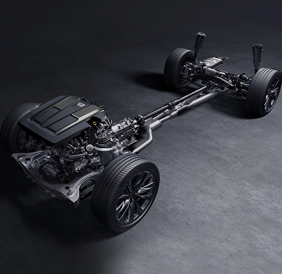
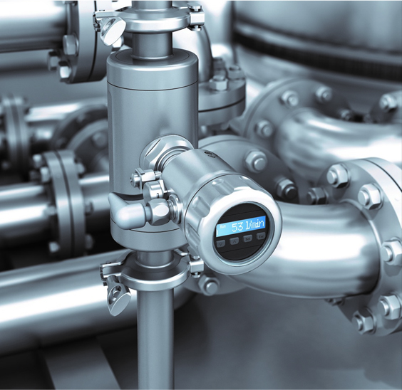
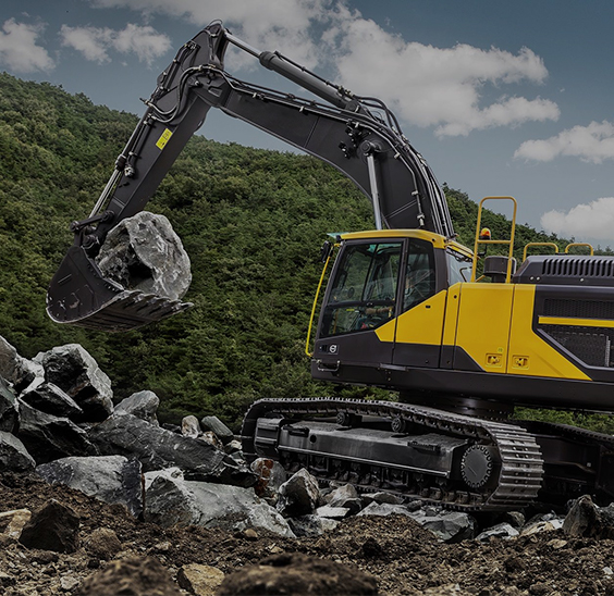
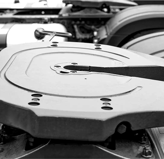
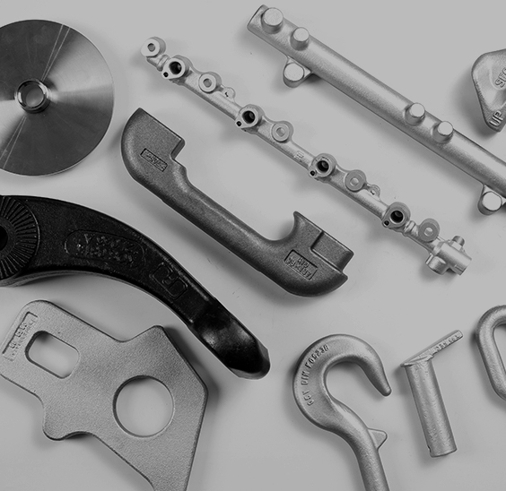
When all these variables are properly controlled, the forging procedure delivers components with mechanical properties and dimensional consistency that no other manufacturing process can match at scale. To explore the full range of precision-forged parts produced across automotive, engineering machinery, instrumentation, and fluid control industries, visit our precision forged components across industries product pages.
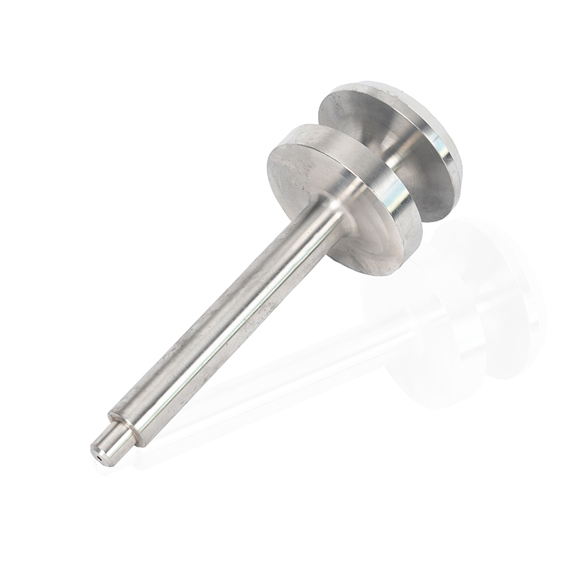
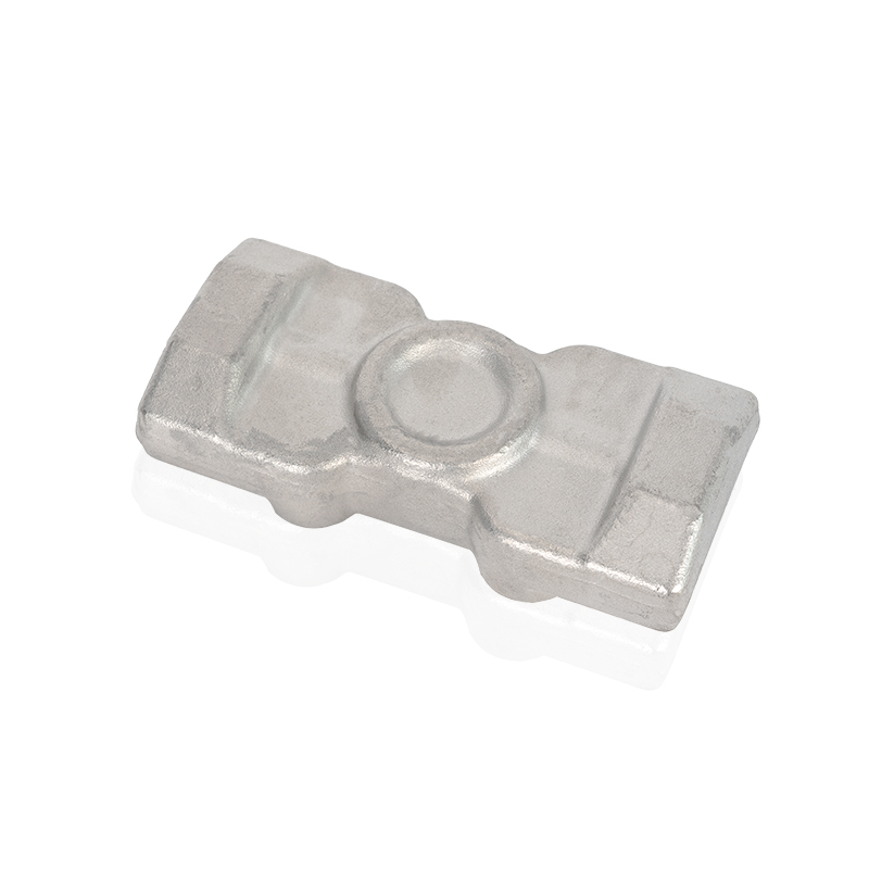
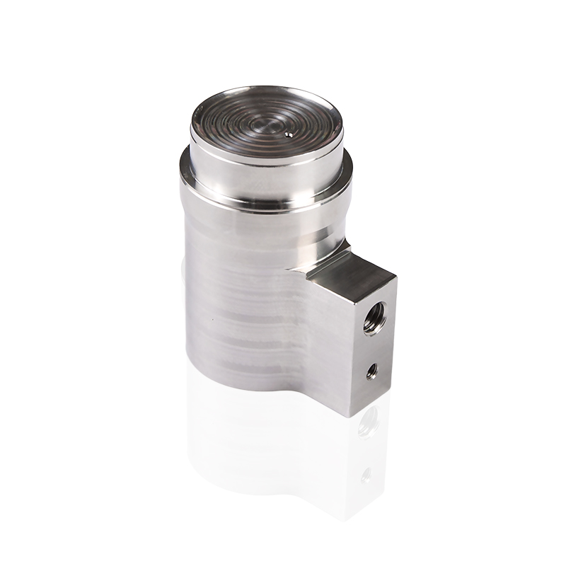
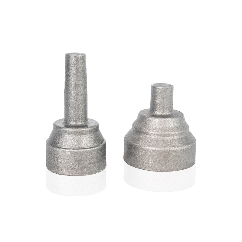
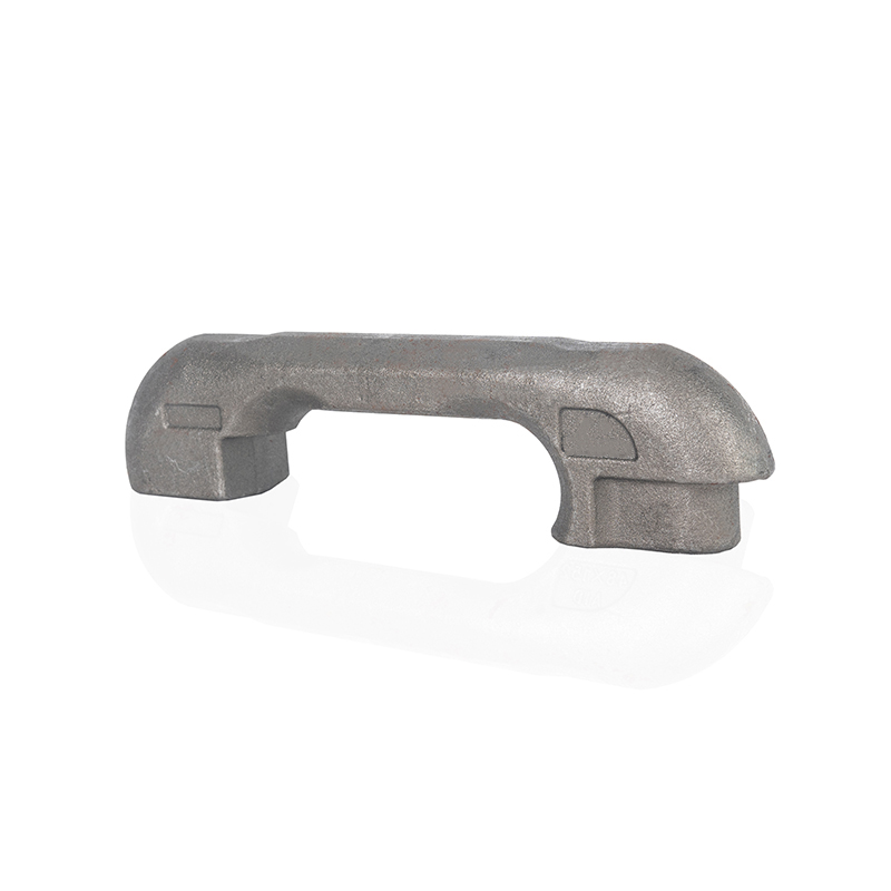
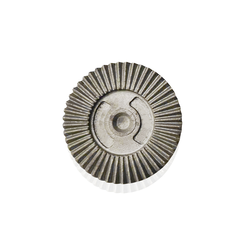
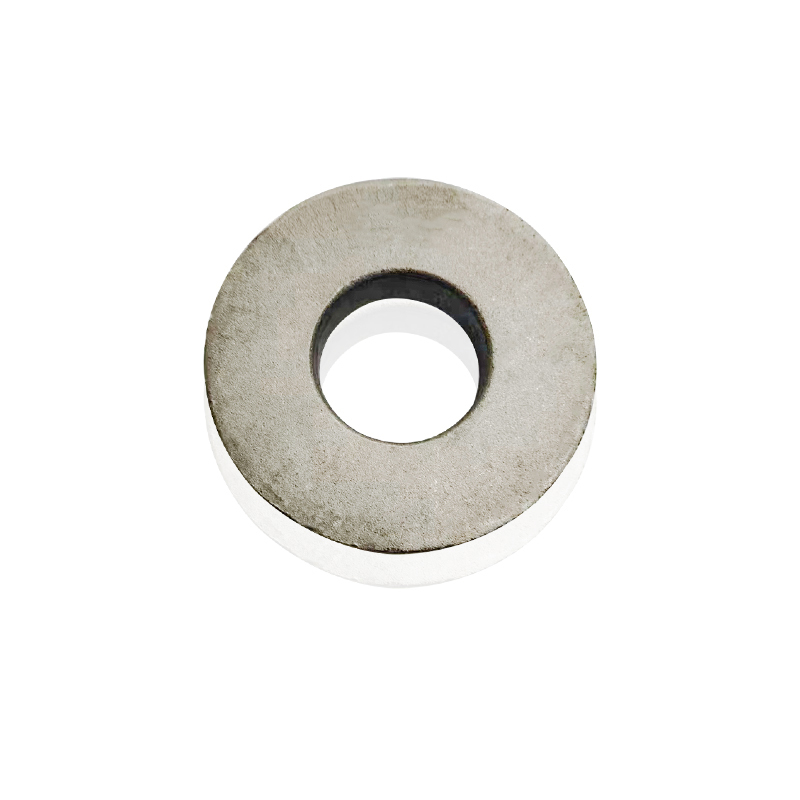
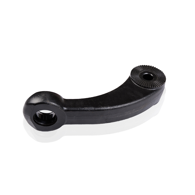
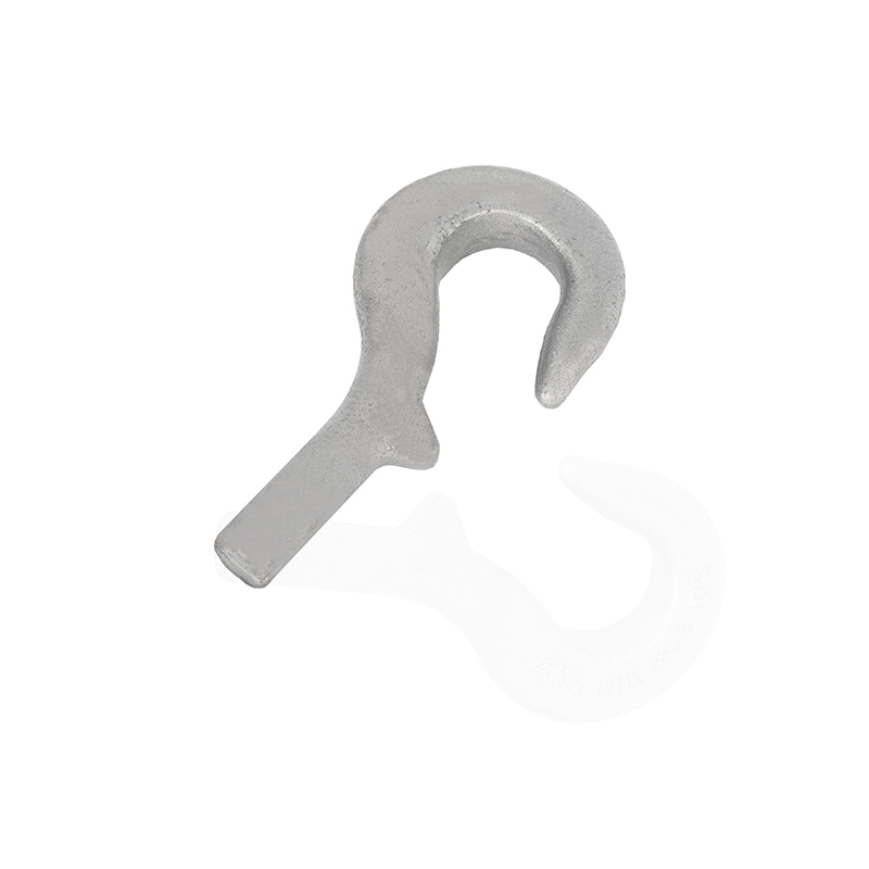
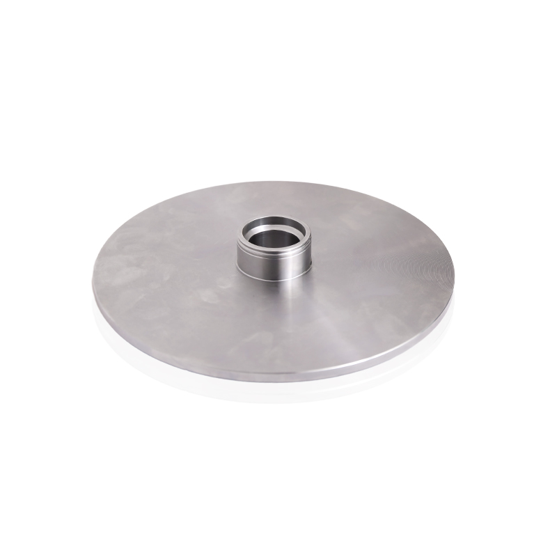
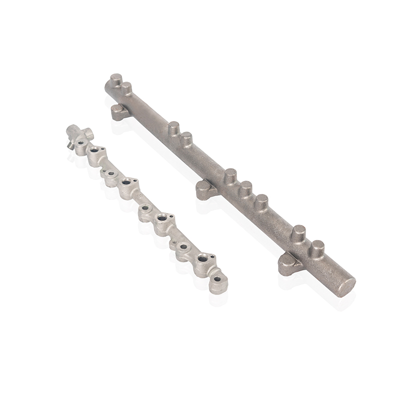
Our products primarily involve the production of forged components for the automotive industry, construction machinery industry, industrial instrumentation industry, and fluid equipment industry. Custom forging parts manufacturers and forged components solution providers in China.
Product links
Contact Us
-
Address:No. 5 Junrong Road, Daitou Town, Liyang City, Jiangsu Province, China
-
Tel:+86-18021979887
